
Kwikstage Loading Bays & Up-and-Over Gates: SWL, Point Loads & Sourcing Guide
Compare Kwikstage loading bay SWL, pallet point loads, up-and-over gate operation and supplier evidence. Use the checklist to prepare a project-specific RFQ.
Kwikstage loading bays have no universal safe working load. Before ordering a bay or an up-and-over gate, obtain an approved configuration that states the allowable pallet load, contact footprint, landing position and operating conditions. A distributed platform rating cannot establish pallet capacity, and a safety gate cannot establish the strength of the tower beneath it. Buyers need both a verified structural package and a barrier arrangement suited to the loading sequence.
This guide is for temporary works coordinators, scaffold hire buyers, importers and contractor procurement teams. It provides a way to compare supplier offers, identify missing engineering information and write an RFQ that can be reviewed against a project drawing. Its added value is the distinction between a supplier’s headline rating and the evidence needed to apply that rating to a particular load and location.
Scope and review date: November 11, 2026. This is an English-language procurement guide for a global audience, not a scaffold design, installation instruction or certification. UK and Australian sources below have different jurisdictions. Check the destination’s applicable rules and project-specified standards and editions with the responsible designer. No physical product testing or customer case study is claimed here; the numerical examples are reproducible arithmetic with stated hypothetical inputs.
Start with the component families for Kwikstage standards, ledgers and transoms, and steel scaffold planks. For a quotation, send the intended configuration and destination to our commercial inquiry desk. Ask the supplier to identify which components and documents are included, and which engineering approvals remain with your project team.
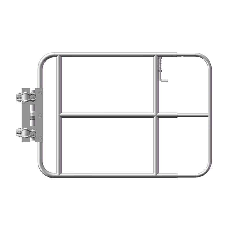
Image identification: The header image is a product render of a single-leaf spring-return scaffold gate. It is shown for comparison and does not depict a complete up-and-over loading bay or demonstrate a load rating. The schematic below explains the intended dual-barrier operating sequence separately.
1. Up-and-Over Safety Gates: Protect the Complete Loading Sequence
The procurement question is what separates people from the exposed edge while material is being landed. A closed gate photograph answers only one operating state. Request a drawing or demonstration of receiving, retrieval and transition positions, including how the operator reaches the handle and how slings or forks are removed without entering a restricted zone. Do not specify a gate solely by its overall width.
In a linked up-and-over arrangement, raising the outer barrier deploys an inner barrier that restricts worker access to the landing zone. After delivery, the outer barrier closes before the inner barrier allows retrieval. Exact sequencing and any locking or interlocking provisions depend on the model. The arrangement still needs checks for gaps, side access, crushing points, overhead travel and obstruction by the load. A counterbalanced mechanism reduces operating effort; it does not eliminate all fall or handling hazards.
A chain or single swing leaf alone does not keep workers separated from an open landing edge. However, describing every such gate as universally banned would overstate the evidence. Specify the protective function and obtain approval for the complete arrangement. HSE’s scaffold guidance calls for suitable loading bay fall protection, preferably gates that can be moved safely for material placement.
2. Point Loads vs. Uniformly Distributed Loads: Read the SWL Conditions
Uniformly distributed load, or UDL, is expressed as force per area, commonly kN/m². A pallet transmits force through its actual bearing surfaces, which may be narrow timber runners rather than its full footprint. The deck then transfers that force to particular transoms, connections and standards. Two pallets with identical gross mass can impose different local demands if their runners or landing positions differ. Include packaging and any retained lifting attachment in the load information supplied for review.
A reproducible screening example, not a design calculation
Suppose an illustrative deck measures 2.44 m by 1.27 m and has a hypothetical UDL rating of 4.5 kN/m². Its area is 3.0988 m², so the equivalent uniformly spread force is 13.9446 kN. Using gravitational acceleration of 9.81 m/s², that corresponds to approximately 1,421 kg of mass. This multiplication does not establish permission to land a 1,421 kg pallet at mid-span or next to an edge.
Illustrative force conversion
Static weight = mass × 9.81 ÷ 1,000
For a hypothetical 1,800 kg pallet: 1,800 × 9.81 ÷ 1,000 = 17.658 kN.
If a designer were to specify a 1.25 landing multiplier for that load case: 17.658 × 1.25 = 22.0725 kN before other actions are considered.
The multiplier is an example input, not a universal code requirement. This is neither a total design action nor a per-leg reaction or an approved SWL. The designer determines applicable combinations and resistance checks without double-counting factors.
Ask whether a quoted value is an allowable working load, a characteristic action, a factored design action or a test result. They are not interchangeable. A proof load also needs its test arrangement, acceptance criteria and relation to the declared working configuration. Neither an EN platform class nor a generic Australian duty label assigns a universal pallet mass, transom section, gate type or standard-doubling rule to every Kwikstage bay.
| Supplier claim | What it establishes | Evidence still needed |
|---|---|---|
| UDL in kN/m² | A distributed-load condition for a stated arrangement | Concentrated loads, pallet contacts and permitted position |
| Maximum pallet mass | A limit only within its declared conditions | Footprint, runner spacing, orientation and landing method |
| Platform load class | A classification under a named standard and edition | Confirmation that the proposed loading operation is covered |
| Transom capacity | Member performance at stated span and supports | End connections, eccentricity and deck load distribution |
| Multiple loaded lifts | A proposed operating arrangement | Simultaneous loading, leg reactions, ties and foundations |
| Proof-test certificate | A result for the identified specimen and test setup | Traceability and applicability to the supplied configuration |
| Gate rating or conformity claim | A claim about the identified barrier assembly | Supporting deck SWL, interface details and operating sequence |
3. Structural Load Paths: Transoms, Knee Braces and Standards
Follow the load from the pallet runners through the decking, bearers, transom ends, nodes, standards, jacks and foundations. At every transfer, request the relevant configuration detail. A stronger beam does not establish a stronger end connection. A second standard contributes only through a defined connection and load-sharing arrangement. Material grade by itself says nothing about unbraced length, eccentricity or connection slip.
Knee braces can change the support conditions and forces in a transom, but their position, attachments and horizontal reactions require design. Do not buy an improvised brace package on the assumption that it provides a fixed percentage improvement in deflection. Similarly, nominal tube diameter or a steel grade label does not demonstrate compatibility with a particular V-pressing, wedge or ledger system. Ask for interface dimensions and written confirmation of the intended combination.
Deck overlays and material handling
Plywood or timber overlays may protect a surface or distribute contact forces, but their thickness, support, fixing, moisture condition and added weight matter. Do not assume an unverified sheet spreads a runner load across a specified number of planks. If pallet trucks are proposed, submit wheel loads, travel routes and clearances as separate inputs. Their use is not implied by a rating for a stationary pallet.
| Component | RFQ evidence | Discrepancy to resolve |
|---|---|---|
| Loading transom | Span, section, support and end-connection detail | Beam-only rating offered for a complete assembly |
| Standards | Tube specification, lift geometry and any doubling detail | Steel grade used as a substitute for stability verification |
| Knee braces | Geometry, connection type and design forces | Unspecified attachment or interference with access |
| Decking | Plank span, retention and local contact-load checks | UDL-only evidence for narrow pallet runners or wheels |
| Plan and vertical braces | Layout and connectors identified on the drawing | Delivery access requiring removal of a designed brace |
| Base jacks and spreaders | Reactions, extension limits and bearing design | Catalogue jack capacity without foundation verification |
Use these two tables to mark each supplier response as documented, clarification required or excluded from supply. Before comparing total prices, reconcile the component schedules against the same drawing revision. If your scope is incomplete, send the configuration and missing-document list for a supply review. This makes a commercial response useful without treating it as site engineering approval.
4. Bracing, Facade Ties and Foundation Reactions
Loading introduces more than vertical weight: load position, handling forces and wind on the gate can affect stability. Plan bracing and vertical bracing provide restraint only through their specified connections. Check that the drawing accommodates the gate’s swept area, delivery opening and required access without removing structural members. A loading tower can also affect the adjoining scaffold, so the interface belongs in the same review.
Obtain the tie layout, tie forces, anchor specification and verification method for the actual substrate. Do not assume ties are required at every lift, or that a generic facade pattern is adequate. The HSE scaffold design section distinguishes tube-and-fitting configurations under TG20 from system scaffolds following manufacturer guidance. TG20 is not blanket approval of an arbitrary proprietary Kwikstage arrangement.
A bearing-pressure example with explicit limits
If a designer supplies a hypothetical 45 kN reaction at one leg, a 150 mm by 150 mm base plate has an area of 0.0225 m². Dividing 45 by 0.0225 gives 2,000 kN/m², or 2,000 kPa, at that contact area. The reaction is an assumed input; it is not derived by dividing a pallet weight among four legs. Actual reactions depend on load location and structural behaviour.
For an assumed allowable bearing pressure of 100 kPa, the simple ratio 45/100 gives 0.45 m² of effective bearing area. This is a screening calculation, not a sole-board sizing instruction. Spreader bending, ground variability, settlement and nearby voids still require checks. On a suspended slab, obtain verification of the supporting structure and any required back-propping. A base jack’s catalogue rating cannot answer those foundation questions.
5. Importer and Contractor Factory Acceptance Checklist
Agree acceptance criteria before placing the order. A useful factory acceptance plan identifies the drawing revision, inspected sample, measurement method, acceptance limit and responsible signatory. The following ten checks are procurement prompts, not universal dimensional tolerances or a substitute for an applicable conformity assessment. Record discrepancies and their disposition rather than accepting a general statement that the product is heavy duty.
10-point loading bay and gate QA checklist
- Configuration identity: Match drawings, bill of materials, supplied lengths and gate model to one approved revision. Identify substitutions before packing, including fittings that look similar but belong to another system.
- Rating evidence: Trace the declared load conditions to calculations or relevant test reports for the complete configuration. Confirm pallet position, simultaneous loading and any handling restrictions are stated.
- Material traceability: Match specified grades and dimensions to mill certificates and production batches. Use the acceptance requirements in the purchase specification; do not treat Q345 and Q355 labels as interchangeable proof of capacity.
- Weld quality: Check weld details, procedure and inspection records against the agreed specification. The designer or relevant fabrication requirements determine acceptance criteria and any non-destructive testing method and extent.
- Coating: Record the specified coating standard, article thickness and measured results. For hot-dip galvanizing, apply the relevant ISO 1461 requirements where specified; 85 µm is not a universal minimum for every steel thickness or article type.
- Gate fit and travel: Assemble a representative unit on its specified supports. Check aperture, pivot alignment, handles, travel envelope and interference using the manufacturer’s tolerances and operating instructions.
- Barrier sequence: Demonstrate receiving, transition and retrieval states. Verify the intended separation from the edge, side gaps, infill and toe protection against the approved arrangement, including the stated pallet envelope.
- Counterbalance retention: Inspect retained weights, springs or gas struts and their fasteners against the manufacturer’s detail. Record operating effort and required maintenance using agreed limits, without inventing a universal force threshold.
- Compatibility and retention: Check wedges, nodes, couplers, deck hooks and anti-lift provisions against the component schedule. Trial fit-up verifies geometry; it does not independently verify structural performance of a mixed system.
- Handover and packing: Include operating instructions, traceable identification, maintenance information and project load signage details. Protect pivots and small fittings in transit, and reconcile the packing list with the accepted component schedule.
6. Inspection, SWL Signage and Site Operating Rules
For UK construction scaffolds, HSE describes competent-person inspections before first use, at intervals of no more than seven days, and after circumstances that could jeopardise safety. Do not export this interval as a global rule. Australian buyers should use applicable state or territory requirements and the project inspection plan; Safe Work Australia’s scaffolding overview identifies inspection and maintenance duties and directs readers to their regulator.
Include checks after impacts, alterations, suspected overloading and weather that may affect the installation, using the applicable plan. Do not infer that operation is safe below an invented universal wind speed. A damaged gate, missing brace, unexplained settlement or unclear load limit should trigger restriction of use and assessment by the responsible competent person before release.
Load signage should communicate the approved configuration’s conditions in terms the delivery team can use: maximum load, permitted position, number of pallets or loaded lifts, and restrictions on people or handling equipment. Distinguish total platform load from allowable material load. If both mass and force are shown, keep units consistent: 2,000 kg has a static weight of approximately 19.62 kN, not an independently verified 20 kN concentrated-load rating. Agree the wording with the design and operating plan.
7. Frequently Asked Questions
1. What is an up-and-over scaffold loading bay safety gate?
It is a linked barrier arrangement intended to separate workers from the exposed landing edge during material delivery. In the receiving position, the inner barrier restricts access while the outer barrier opens; for retrieval, the outer barrier closes before workers enter. Verify the actual operating sequence, clearances and instructions for the supplied model. A gate does not establish the supporting platform capacity.
2. Is every single-leaf swing gate prohibited on a loading bay?
Do not infer a global prohibition from a gate name. A single swing gate alone does not isolate workers from an open landing edge while receiving a load. The applicable site rules and risk assessment must establish suitable protection throughout the operation. Specify the required barrier function and obtain acceptance of the complete arrangement before procurement.
3. What is the safe working load of a standard Kwikstage loading bay?
There is no universal loading bay SWL attached to the Kwikstage name. Use the manufacturer configuration or competent designer’s approved drawing for the exact bay, height, deck, supports, bracing and load position. Ask whether the stated limit covers a pallet, total platform load or distributed load, and whether workers, handling equipment and landing effects are included.
4. Can I convert a UDL rating into an allowable pallet weight?
Multiplying UDL by deck area gives an equivalent total force for a uniformly spread load. It does not verify a pallet carried on narrow runners, individual plank bending, transom reactions or the landing load case. Obtain concentrated-load and contact-area checks for the actual pallet position before accepting a pallet rating.
5. When are double standards or knee braces required?
They are required where the approved configuration specifies them. There is no universal three-lift height trigger or tube-grade shortcut. The designer checks member stability, connection forces, load eccentricity and support conditions. Adding a brace or second standard without checking its connections does not automatically increase the bay SWL.
6. How often should a Kwikstage loading tower be tied?
Follow the system manufacturer’s instructions and the approved loading bay design. Obtain tie positions, design forces, anchor details and substrate verification. A facade tie grid, an every-lift rule or a nominal anchor diameter cannot be transferred to another loading tower without checking its geometry and load cases.
7. Does a 1.25 landing factor prove that a loading bay is adequate?
No. Landing effects depend on the handling method and the design basis. Any factor must be justified for the intended operation, and checked alongside the applicable load combinations, member resistances and connection details. An illustrative multiplier is not permission to drop a pallet or a substitute for a project design.
8. What evidence should an importer request before shipment?
Request the configuration drawing and revision, component schedule, declared load conditions, gate instructions, relevant test reports and inspection records. Match material certificates and weld and coating records to identifiable production batches. Agree acceptance criteria before manufacture, including functional operation, compatibility and retained counterweights or springs. Release unresolved safety or rating discrepancies to the responsible designer for disposition.
8. Sources and Evidence Boundaries
Sources checked November 11, 2026. These public pages support the jurisdiction and planning distinctions cited above. They do not certify a product, prescribe the hypothetical example factors or establish a universal Kwikstage SWL. Obtain the project’s applicable standards, manufacturer manuals and approved design separately. Recheck this guide when those documents or the proposed configuration change.
- UK Health and Safety Executive: Scaffolds. Public guidance on design routes, loading bay protection and scaffold inspection. Its UK requirements should not be read as global rules.
- Safe Work Australia: Scaffolds and scaffolding work general guide. Guidance for managing workplace scaffolding risks, with downloadable resources. The publisher classifies it as a guide, not a model code of practice.
- Safe Work Australia: Scaffolds and scaffolding overview. Covers duty holders, risk management and inspection resources, with referral to state and territory regulators for local requirements.
Prepare a Comparable Loading Bay RFQ
Send the destination market, project drawing revision, bay dimensions, lift heights, maximum pallet mass, runner dimensions, landing method, gate opening and component quantities. Add the existing fleet identity, required finish, documentation requirements and delivery schedule. Mark unknown inputs as awaiting design review instead of filling them with a catalogue default. This lets suppliers price the same scope and identify exclusions before a purchase order is issued.
Compare the supplied standards, transoms and ledgers, and deck planks against that schedule; use our Kwikstage packages catalog for broader component planning. A general package listing is not evidence that a particular loading bay is approved.
When the scope is ready, request component pricing and supporting documents. Ask for a clear statement of supply scope, rating evidence and items requiring further project review, so the commercial offer can move forward with its engineering assumptions visible.